Tail Pivot and Boom
The tail needs to pivot 90 degrees in order to keep the blades flush with the wind and to move them close to 90 degrees out of the wind (blades parallel with wind direction). This is called furling and is needed to protect the rotor from an overspeed condition when the wind is too strong for the turbine. The rotor is slightly to the left of center, so when the wind pushed on the rotor there is a moment arm that wants to turn the turbine assembly around counter-clockwise if you are looking straight down on the turbine from above. The tail keeps the turbine in the wind. However, if the tail was truly parallel with the wind there would be no tail area for the wind to push against to create a restoring force to offset the rotor moment-arm. Therefore, the tail in its resting state is angled slightly to the right by about 5-10 degrees. Now there is some tail surface area that is hit by the wind. This is accomplished by placing the tail pivot at 45 degrees counter-clockwise from the assembly. The pivot is angled backwards by about 20 degrees. We also don't want the tail to furl exactly 90 degrees to the turbine axis or the tail will hit the blades. We only want it to furl about 80 degrees. This will leave enough space between the blades and the tail.
Now let's continue our discussion about the tail pivot and the 45 degree angle. If we let the tail boom pivot freely it would settle 45 degrees counter-clockwise and 20 degrees downward. The 20 degree backward angle allows gravity to pull the tail boom down. We cut the pivot with a stop on one side the gravity can only pull the boom about 10 degrees counter-clockwise.
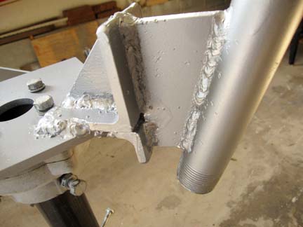

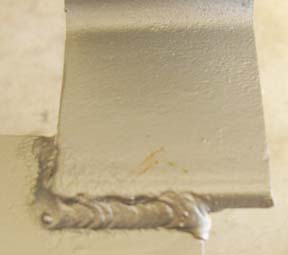
On the left is the tail pivot made from 1" schedule 40 tubing. It is welded 45 degrees counter-clockwise from the turbine axis. The boom bearing, made from 1.25" schedule 40 tubing fits over it. The tubing is cut with a metal grinder and the scrap is welding back on to reenforce the stop. I would guess about 120-130 degrees are cut out from the tube. If the metal holding the tail pivot had no thickness and the welds occupied no space we would only need a 90 cut on the tubing. However, the welds and the steel thickness necessitates that we need about 120-130 degrees cut out. Now some will weld a stop on the assembly or tail boom to prevent the tail from swinging into the blades. I welded a stop on the opposite side and grinded it down so the bearing controls the degree of all tail boom motion.
I weld the boom to the pivot so it is 10 degrees counter-clockwise from the turbine axis in its resting state. The pivot is cut so it allows 90 degrees of clockwise motion so the tail finishes 10 degrees short of being parallel with the rotor.
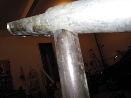
I just put this image in here to show how my welds have gotten better with practice.
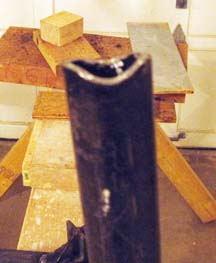
The tail boom is welded to the pivot. I took a 1" schedule 40 pipe that was 5' long and cut a 20 degree angle into the half of the end and left the other half alone. I then used a Dremmel to grind curves on both sides. The right picture shows how nicely I have coped the pipe. I will now weld this together.