Phase Locked Loop (PLL) Basics
A PLL consists of three parts: a voltage controlled oscillator (VCO), a loop filter and a phase detector. The VCOout drives the device, or inverter gate in our case. It also closes the loop by feeding itself back into the phase detector so it can get compared with a reference signal.
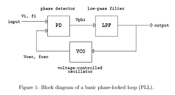
The VCO generates a 50% duty cycle square wave; the frequency depends on the input voltage to the VCO. The higher the VCOinput (pin 9) voltage the higher the VCOoutput frequency; the lower the voltage the lower the frequency. The PLL phase detector compares the phases of two inputs: the reference signal on pin 14 and the VCOout frequency. The phase detector has two options for outputs: PCA1 and PCA2. We use the former, which is a XOR gate.
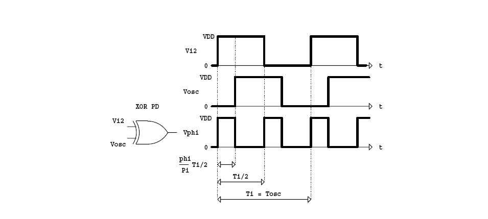
Figure 2
The logic is high if one of the two inputs is high; otherwise it is low. It will generate a square wave whose width is based on the phase difference of the two signals. If the two waves are 90 degrees out of phase the average value of Vphi is Vdd/2. The loop filter takes the phase detector output and converts this to the input voltage to the VCO. The simplest filter is a RC low-pass filter. The cut-off frequency will determine how sensitive the PLL is to phase changes, and how well it stays locked on the reference signal.
So what happens? At resonance the tank current is real and in phase with the coupler transformer voltage, which is in phase with the inverter voltage. The tank capacitor voltage lags the tank current by 90 degrees; therefore, it lags the inverter voltage by 90 degrees. Now as the workpiece heats its ferromagnetic properties change. The workcoil becomes a variable inductor and affects the resonant frequency of the tank. If the effective resonance goes down, it seems to the circuit that we increased on drive frequency to the tank. This makes the tank more inductive. Inductance causes the source voltage lead the tank current. That is, the tank current is forced to lag the inverter voltage. The capacitor voltage initially lagged the current by 90 degrees. This means the capacitor voltage lags the inverter voltage even more as shown below.
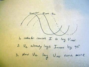
Figure 3
Below we can see the relationships with Vinv, Vcap and Vphi. Vphi is high Vinv or Vcap is high, but not both.

Figure 4
The top shows Vinv and Vc. An increase in inductive reactance is the same as if we increased our inverter drive frequency. We lower it by decreasing the voltage to VCOin. We see in the top pair that as Vc shifts more to the right of Vinv the XOR region increases. However, we need it to decrease in order to yield a lower voltage for VCO. We achieve this by inverting Vc to Vc_inverted. Now as Vc_inverted shifts to the right, Vphi decreases. We integrate this to a voltage value and use this for VCOin. A smaller VCOin results in a lower frequency and we stay in resonance. The frequency range is determined by resistors on pins 11 and 12 of the PLL. When, VCOin is at ground the frequency is at the low-end of the range; when it is at the supply voltage it is at the high end.
When we are at resonance - inverter voltage and current are in phase - the inverter voltage leads the tank capacitor voltage by 90 degrees. Vphi is half of half a pulse width (see Figure 2 and 4). The average voltage is Vdd/2, or 7.5v if our supply is 15v. So, 7.5v at VCOin will keep us close to resonance if our center frequency is Fres. The problem is that Fres changes with different workpieces and during heating. However, the PLL will adjust itselft to maintain a lock on the phase relationship.
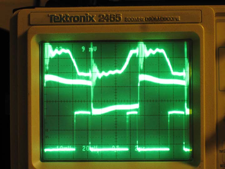
The scope images below show these waveforms. The first picture is at a lower frequency than the bottom picture. Shown are Vcap_inverted, Vinv, and Vphi. The capacitor voltage is clipped to protect the PLL chip.
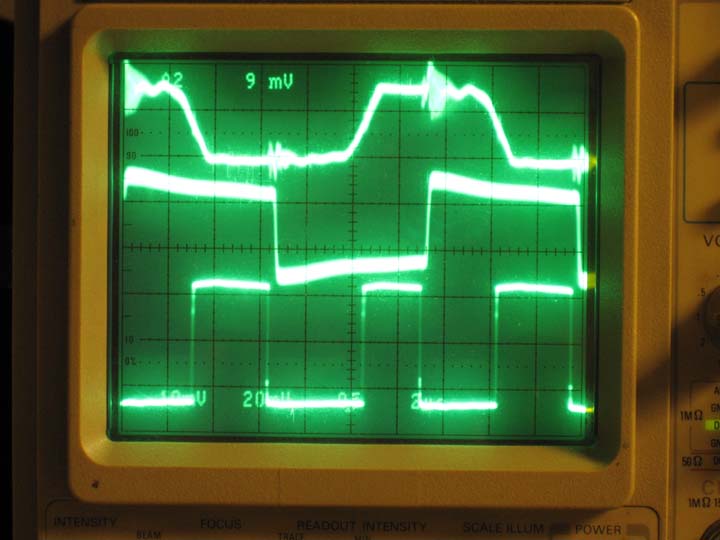
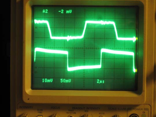
The capacitor voltage is a clean signal, and was distorted when I tried to show three signals. Below is just the inverter and tank capacitor voltage.
We need to discuss a few more things about the PLL next.